 |
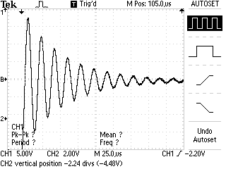
Measurement of InductanceIn this lab experiment we will measure inductance of a solenoid. The first way we will do this will be to measure the time constant tau of an RL circuit. This is a repeat of the measurement of the time constant in an RC circuit with an inductor in place of the capacitor. In your pre-lab you should should note why an RL circuit will have a time constant the same way an RC circuit will. For this week's experiment you will need an inductor, a resistor, a function generator, a DMM and an oscilloscope. For the inductor and resistor, we will use a PASCO RLC circuit board. Wire up the inductor and resistor in series. Once this is done, put the inductor and resistor in series with the function generator and set the output of the generator to give you square waves. At this point you should use the oscilloscope to view the voltage across the resistor. You should see the same waveforms you saw in Lab Six. Repeat the measurements you made several weeks ago. Find the peak-to-peak voltage, calulate Vo * e-1 and then make a "one point" estimate of the time constant. Then export the data and plot time vs. ln voltage (you did remember to bring your USB memory stick to lab, right?). The slope (or the negative) will give the time constant. Compare the uncertainties between the two different methods and report a value for L. While one lab partner is graphing the data from the decay part of this experiment, the other should be setting up an RLC circuit. The solution on an RLC series circuit has two terms that multiply, one that expresses an exponential decay that represents the power loss due to the resistance, and a sinusoidal fuctions that accounts for the exchange of energy between the capacitor and the inductor.
The constant that multiplies time in the decaying exponential is -R/2L and the natural frequency
of oscillation is (LC)^-.5. If the exponential constant is small compared to the natural frequency,
then the voltage across the resistor will oscillate, each time hiting a smaller maximum value.
This is known as underdamping.

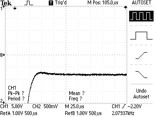
If the exponential constant is much bigger than the natural frequency, then no oscillations occur and the function simply decays. This is known as overdamping. The switchover in behavior takes place when the two terms are equal: C R^2 = 4L
The next screenshot shows a circuit near critical damping:

Today you will set up a series RLC circuit using a decade resistance box, a decade capacitance box and your inductor. Use the function generator as a power source, and use square waves at roughly 300 hertz. Observe the voltage across the resistor. Vary the capcitance from 0.001uF to .011uF, and record the value of R for critical damping. Graph C against R^-2 and report a value for L. How does this compare to your other values? |